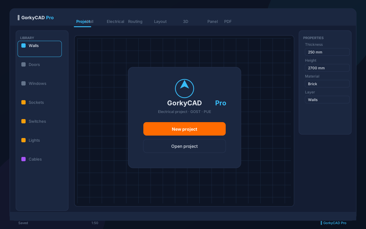
Step-by-step guides for every tool: walls, electrical, routing, panel, single-line diagram and PDF export. Design follows the steps in the toolbar above the canvas.
1. Walls and furniture ("Furniture" step)
How to draw a wall: open the "Furniture" step → the "Wall" tool → click on the canvas and drag a line. Hold Shift for straight 0°/90° angles.
Doors and windows: select "Door" or "Window" in the left library → click on the wall — the opening will snap to the wall and appear in the right place.
Dimensions: the "Dimension" tool → click two points → a dimension line is placed.
Wall thickness is set in the properties panel (250 mm by default).
Wall materials (brick, aerated concrete, gypsum board, etc.) — for correct hatching and specification.
Rooms are recognized automatically from the closed wall contour.
2. Electrical ("Electrical" step)
Outlet: the "Electrical" step → "Outlet" → click on the wall. The symbol automatically snaps to the wall.
Switch: "Switch" → click on the wall near the door. The switch snaps to the nearest lighting group.
Light: "Light fixture" → click in the center of the room. Lighting groups use a dedicated 10A breaker.
Symbols comply with GOST and are available in the left library.
The interface suggests optimal locations per PUE rules (outlet heights, wet zones).
Devices are grouped into circuits automatically (auto-circuits) considering loads.
3. Cable routing ("Routing" step)
Cable: the "Cable" tool → connect a device to the panel. The route is drawn automatically along the optimal path (orthogonal, avoiding walls).
Route length is calculated automatically (horizontal + vertical drops).
Cable cross-section is selected by calculation (PUE tables 1.3.4–1.3.7).